|
|
Post by smallspeed on Jul 25, 2017 7:33:56 GMT
On to the bottom-end.. The block was cleaned using the same "ice-blasting" technique, as was the sump, oil pump parts, etc. The crank (now fully balanced) was dropped into the block and torqued down using a set of cheap standard main bearings, and the old cap-bolts, and the joints measured using plastigauge strips. Most of the bearings were showing in-tolerance clearance, however a couple were towards the top end, and so a "custom set" of main bearings were ordered from BMW - they offer various colours of bearings relating to how far oversize they are - red, yellow, green, blue, etc. They offer these individually, and in standard, first ground and second ground fitments too, so it’s pretty easy to get them right! Bearings in, crank was assembled and re-checked with another set of plastigauges - clearances all now at the bottom end or thereabouts  Plastigagues removed, everything cleaned and suitably lubricated with an assembly lubricant, torqued down with new bolts, pistons and con-rods fitted, again with "correct colour bearings"  At this point I set the crank to piston 1 TDC and found the best way to do this was with a dual dial test gauge - I'm not sure what the correct term is for this thing, but it’s used for levelling the bed of a milling machine and looks like this.. 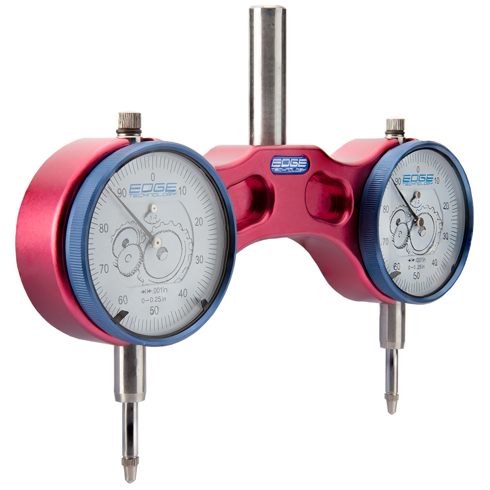 ..I was able to stick it on pistons 3/4 which are level at piston 1 TDC, and then lock it out I thought this was a really neat piece of kit, but the guy I borrowed it off remembered I had borrowed it so I had to give it back  I've since brought one of these.. 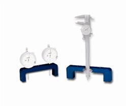 ..which is about 1/10th the price of the first thing, and works really well for setting piston 1 (although not on aluminium blocks!) All set and ready to go, crank locked out against the block..  Lower timing case on..  Cams set to TDC and locked out, head, oil pump, (metal*) water pump, and upper timing case on..  * A lot of BMW engines run a plastic impellor on their water pumps and they're a bit of a ticking time-bomb. I think they're OK if they're replaced every 50k or so, but they're a risk either way, so if you're replacing one get either the later version which has a metal impellor, or an aftermarket one with a metal impellor - there are a couple of versions, one with a welded steel arrangement and the other with a cast aluminium one. I prefer the latter, it looks WAY more robust to me and mimics the plastic impellor design Now we take a bit of a leap!.. Head on, all timed up, vanos unit fitted, cam cover fitted, COP's in, everything snugged down and wired up!  Exhaust manifold "art"..   These are from the "Euro" e36 m3 evo (S50B32) and are about as good as it gets really - there are a lot of third party performance exhaust manifolds (or headers if you're American) however none of them really perform better than the factory manifolds.. The S50B32 was a proper 100bhp/litre engine (first naturally aspirated standard production engine to achieve it I believe) so they weren't messing about :lol: I know of some big power race engines using these manifolds, so they're not going to be a restriction for my little 2.9  And, wrapped..   I asked a lot of questions about wrapping vs. paint and wrapping vs. coating, etc., and ended up deciding coating was not going to fly on my budget, or on second hand manifolds without a lot of cleaning inside and out! I got a top tip from Mr Race-Mechanic next door though - use the titanium wrap! Apparently the standard black / white / cream stuff is nasty to fit, and a lot of people recommend doing things like soaking it in water before fitting, painting over it, painting under it, etc. All seem to either make the wrap degrade, the wrap catch-fire, or the manifolds rot over time.. Titanium wrap - fit it, move on! He then proceded to produce 30 meters of the stuff from a box in the garage and give it to me, saving me about £100.. He then stood and watched me wrap the damn things - offered no help, just lots of laughing, tutting, and head-shaking! I think he had his 100 quids worth that morning!! All locked in place with double-loops of double-lock-wire rather than straps (another tip) because it holds everything tight, but add a bit more flexibility vs. the very solid stainless straps Couple more bits and bobs, some wiring, and its ready for fitting!  ENGINE DONE! And pictured on the drive with its 120bhp/litre n/a little sister (s54b32tu) |
|
|
|
Post by smallspeed on Jul 25, 2017 7:37:33 GMT
So with the engine done, the work finally moved onto the diff, which is what kicked all this off.. I apologise but I had a lot of phone trouble when I was doing the diff and I don't have many pictures - the trouble was mostly that I went to Peru with work for a week and my phone decided to stay an extra few days before flying back!
e36 6-cylinder non-M cars use a 188mm diff, which is the same ZF "pumpkin" as a few Porsches (I forget which models, but I think 944 turbo / 968 and maybe some more)
Due to the lack of photos, I've robbed some from the internet to explain the internals of the diff and what was done..
This is a nearly accurate image of what the insides look like!
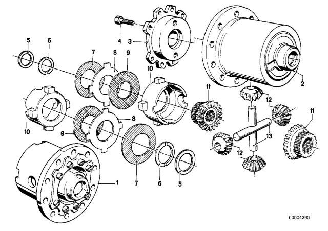
part numbers 1 and 2 are the case or "pumpkin" if you're american! On a 188 diff, part number 2 is actually part of part number 1 - they're not seperable
Part number 3 is the other end of the case and part number 4 is the bolt which holds this to the case. These can fail, will explain more later.. The face showing with the two holes in it top and bottom (which aren't there) is a friction face
Parts 5 and 6 don't exist either they're a single large washer about 2.5mm thich and similar in size to part number 8 but without the ears
Parts 7 are Bellville washers which create some pre-load
Parts 8 are steel plates, the side facing part number 9 is a friction face (think flywheel), the "ears" fit into slots inside the pumpkin
Parts 9 are the friction plates (think clutch plate) - it’s not really show above, but its important to understand, they have a star shape on the inside face which matches and fits over the splines of the main gears going out to the drive shafts
Parts 10 are the carriers or pressure rings - these also have ears which slot into the case. They also have a friction face (think flywheel) which is facing parts number 9, and ramps on the other end which are shown here as nice round cut-outs. More explanation below, but these are actually V-Shaped cut-outs
Parts number 11 is connected to the driveshaft either side
Parts number 12 are the "little gear things" (spur gears?). These mount to the spider #13 which is actually two rods with a cut out in the centre so they sit over each other and form a cross. The ends of these "rods" sit into the V-Shaped cut-outs in the carrier #10
So in operation, the crown wheel (mounted to the large PCD hole array in the pumpkin) is turned by the pinion gear connected to the prop shaft. The whole pumpkin rotates, and torque is transmitted to each wheel via part numbers 11
If there's a difference in torque between the two wheels greater than the "pre load" provided by the Bellville washers (#7) then the two gears (#11) will try and rotate the cross shaft made up of part numbers #13
This rides up the ramps on #10, forcing #10(left) and #10(right) apart. That clamps the friction plate (#9) between the friction faces on parts #8 and #10 either side
Hopefully that makes some sense?!
So a couple of driving factors..
1) pre-load effects when the diff "locks", and also how much drag or loss there is in the system when you're travelling in a straight line
2) The number of friction plates (9) and friction faces (8) effects the amount of lock the differential is able to create
3) the angle of the ramps effects the amount of lock the differential creates
As standard #1 is set somewhere around 19-22Nm, #2 is 2 combination of plates (one per side) and #3 is 45 degrees in each direction. This results in around 25% lock in acceleration and deceleration
While #2 works in both accel and decel, #3 is direction dependant - there's one face for accel and one for decel, so it’s possible to increase or decrease the amount of lock in each direction independently
Here's some examples..
This is a standard set of ramps - 45-degree either way which is a 2 way set-up
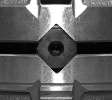
This set of ramps has been re-ground with a very steep angle in one direction (presumably decel). This wil give very little lock in deceleration but more in acceleration. This is a 1.5 way differential
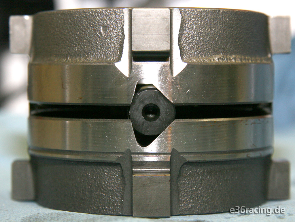
This set of ramps is a 2-way set-up as well but with a very flat ramp angle which gives a much larger lock-up
You can see they've ground a second set of ramps on the right pressure ring which is preferable to re-grinding the standard ramps. The one on the left is actually a "homemade" one they produce at whatever angle you want from scratch
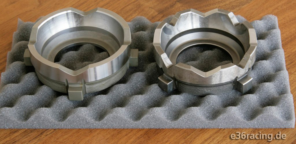
Its also possible to grind the ramps with a vertical face in one direction and a ramp in the other - this is a 1 way differential and only gives lock under (usually) acceleration
If you remember, I mentioned parts 5 and 6 don't exist in the BMW diff - there is however a large washer that is not shown above, and this is the same diameter as a friction plate or clutch plate (part 8 and 9), AND with the same thickness as 1x part 8 and 1x part 9. A really simple "trick" when rebuilding these diffs is just to bin that washer and fit another plate and clutch (8 and 9) which increases your lock to around 35% in both accel and decel. You can go a step further and have the friction face of part number 4 ground down by the thickness of this washer and add another pair of plates (bringing the total to 4) or even more and have 5 plates.. This is a VERY high locking diff, and not very normal, although quite a few people go upto 4 for the small amount of work involved – this is what I did
Here's an example of what the standard and machined end plates look like..

Another trick (if you're doing a BMW diff) is to use the super-duper sintered BMW Motorsport clutch plates. These cost an ARM AND A LEG! What I found though working back through the ZF parts books, is they're the same part number as the standard Porsche clutch plates. Another kick in the nuts - the standard Porsche clutches (from Porsche Leicester) are cheaper than the standard moly clutches from BMW.. Fortunately for me I figured this out before I brought anything, and so was able to build this diff up using those Porsche parts - saving a few quid over the moly BMW parts (and a ton of money vs. the sintered BMW Motorsport parts) and adding a little more bite 
I also mentioned before pre-load - there are a few people who like different values, some preferring zero preload which gives less drag in a straight line but a very harsh engagement, others preferring a lot more preload than standard (45Nm in some cases!). This gives more drag but a more progressive engagement.
I had no idea what I was going to want, so I hit bang on 20Nm which is pretty much standard - we will see how that works out!
Final specs for my diff build:
20Nm pre load
4x clutch plates
45 degree ramps
That little lot gives around 35-40% lock in accel and decel I think which is a nice increase over standard but without going too crazy. Also pretty much standard engagement so hopefully friendly (ish) on road and track
Here's an example of the complete "stack" outside of the diff case to give you an idea what it all looks like..
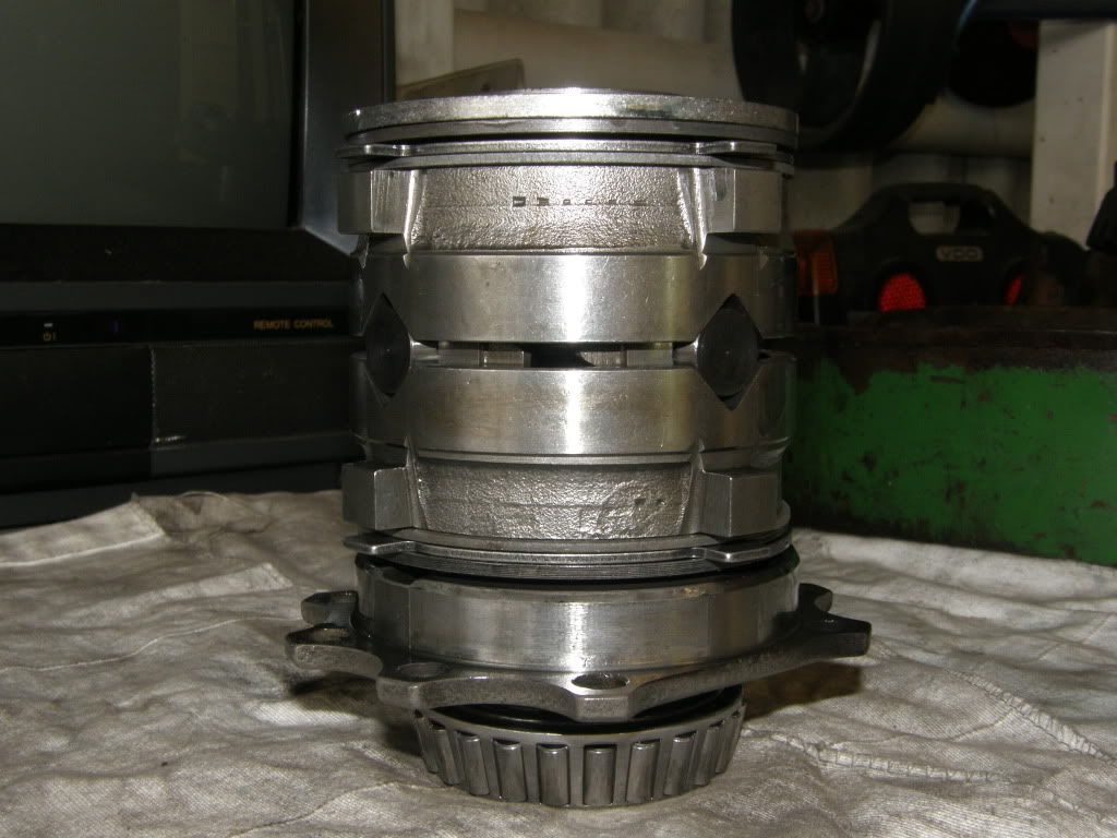
And this is an assembled diff unit complete with new bearings and the trigger wheel for "speed"
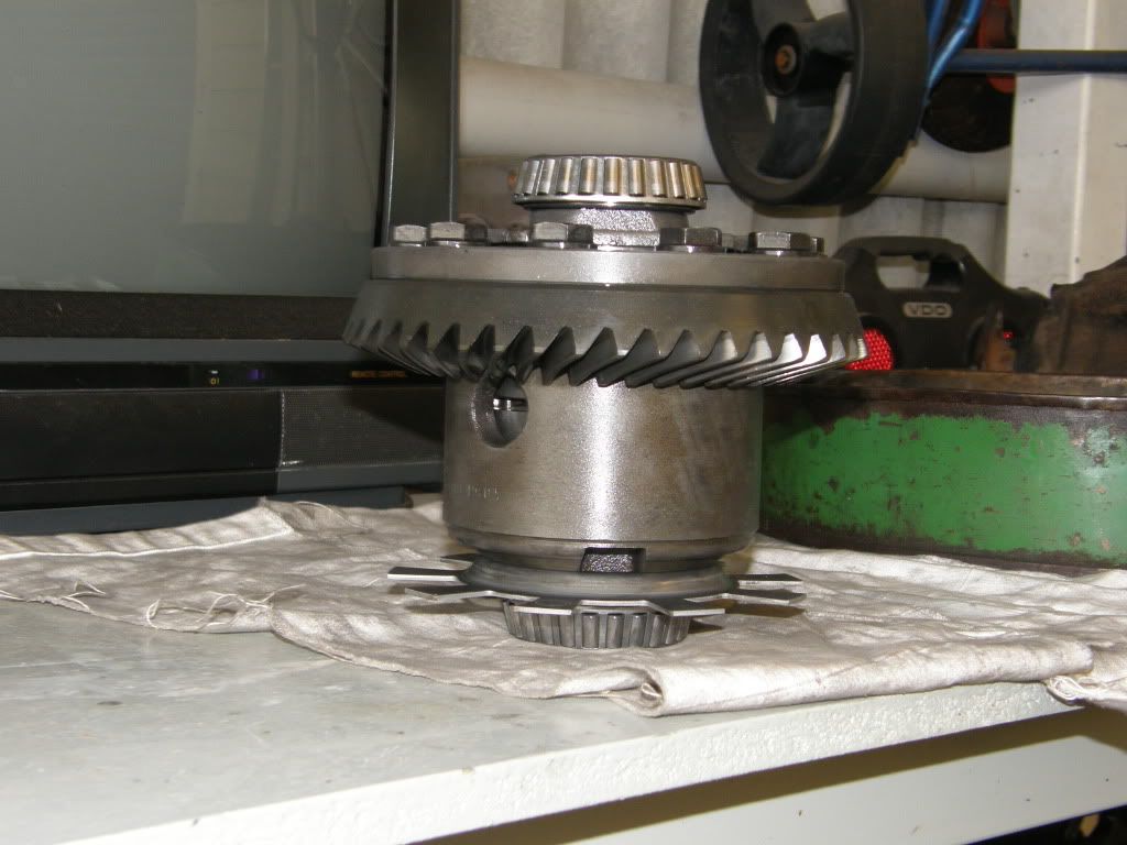
My diff was rebuilt using new bearings, seals, etc., and a new crush washer (more like a collar thing) which is used to set the position from the centre line of the pumpkin to the pinion gear for engagement, and a bunch of new shims which sets the position of the pumpkin (along its centre line) relative to the centreline of the pinion to ensure correct engagement
One other thing I did - I mentioned earlier the bolts can fail which hold the cover onto the end of the main diff casing.. I had all new bolts and got them cross drilled. I know its weak having them done for you, but having brought a jig and snapped about 3 drills and one small end-mill on my pillar drill I gave in! I then loctite'd the bolts per spec, and lockwired for back-up. This was one of those super-anal things i really enjoyed, that should have taken 10mins, but probably took 3hrs!
I also drilled out and re-tapped the front mounting bolt hole - this is an M12 bolt as standard and they've been known to SNAP! There's a lot of speculation whether this is caused by aggressive driving and worn out bushes, or if it’s an actual weakness.. Given BMW went to an M14 bolt on the next gen cars it seemed a no brainer while it was all out of the car, especially since I had an M14 tap already, and was making my own bushes!
Case painted up, new bushes pressed in (thanks to Chris, who's press has never seen so much action until I started this project) and all mounted up back in the car!
After all that, I'm happy to report my phone appeared! So back to MY pictures
This is a test-fit - I machined the bushes myself in the garage so needed to try them up against the back plate to make sure they fit ok.

This is the final back-plate and it’s not a load better to be honest 

For the time being this is using a standard back-plate, however depending on the temps I may fit an "alpina cover" which has a small sump at the bottom and is heavily finned for cooling (or just smash a couple of AN ports in the side of the housing and fit a pump and a separate cooler, per the original group a / stw cars).
I have a temp sensor in the bottom of the housing anyway, so can keep an eye on this 
Next time - "The shell returns and my mrs gets WASTED on the driveway!"
|
|
|
|
Post by duffmanuk300 on Jul 25, 2017 7:49:57 GMT
Coming along nicely, good build
|
|
|
|
Post by smallspeed on Jul 26, 2017 10:39:54 GMT
So, as promised, this instalment covers the roll cage! First up some trauma.. I spoke with the guy next door about roll cages on several occasions, but he only ever used some crazy scottish chap near Banbury who's taken over the old Prodrive rigs and things and does most of their work for them now. Apparently he's "the best" however his price was the best too! I never spoke to him directly, but I have it on fairly good authority he charged around £25k for the shell prep and cage installation for the roger clarke motorsport gobstopper 2.. Now don't get me wrong, the thing is a work of art, BUT I don't have a 25k roll cage budget!.. I set about contacting a bunch of people about rollcages - from some of the largest UK roll-cage companies, to the smallest, and I didn't get a great feeling from many of them. They MOSTLY fit into one of three buckets in my experience.. 1) Potential Arthur Daleys - people who when questioned about technicalities crumble, or try and convince you what you're asking for or expecting is some way irrelevant or incorrect 2) Poor communicators - people who you spend 3 or 4 days getting hold of, are great on the phone, seem to know everything, but ultimately are impossible to deal with (these are likely "craftsmen" rather than "businessmen" which is fine, but it kind of makes my foot itch when someone is that hard to contact) 3) Sellers - people who just want to take your money and give you a load of tubes I had discussions with supposed experts who didn't understand MIG / TIG requirements based on the materials they were using I had discussions with very large companies who claimed all sorts of ISO certification, yet had zero traceability of their materials, inconsistent suppliers, and offered no material or installation certification I had discussions with numerous answer machines Don't get me wrong they are all fine for what they do, but the majority treated me like a dick-head so got written off very quickly. I'm NOT a roll cage expert, BUT I spent a lot of my early years in engineering designing, analysing, developing and validating tubular spaceframe structures including several kit car and sports car chassis so I'm not a complete noob in these matters. Again for some this might be fine, but for me I was specifically looking for someone I could work with, and not someone I could just throw money at and buy something from In the end I tried a guy who might as well be at the end of the earth relative to me (middle of the south-downs national park, Hampshire) and FINALLY found someone on my wavelength! He actually confirmed to me some of my suspicions with a few of the big companies, particularly regards material specifications which isn't good. I'm not going to name and shame; these companies are big and make a good living doing what they're doing, with many happy customers, however I'll never be one of them. He also brought a few things to my attention I'd not considered before, and we had several good 2-way conversations about my car, me, what I was planning on using it for, etc., and came up with a plan! Like I said, I'm not going to bad mouth anyone, but I will sing Nick's praises, and hope that others have similar experiences to mine with whoever they end up choosing... The one piece of advice I can pass on - find someone you're comfortable with using! A roll cage isn't cheap, and it is something you want to work properly!  Nick (Nickson Motorsport) is based here..  ..its a long way from my house, but I wanted a good cage, installed by someone who knew what they were doing so I was prepared to travel Nick immediately started talking my language, understood my budget, came-up with a plan with me on what I'd have where, what I needed, etc. He also seemed far more up to speed on roll cage design than most of the other people I'd spoken with and also had a really good understanding of current and future regulations and specifications - perfect example, the changes being proposed re: door bars, and the potential outlawing of traditional X-Bars (where there's one continual diagonal tube, and two short tubes making up an X, welded in the centre). After George Plasza's fatal accident (in a BMW) people were moving towards door bars that were an X made from two continual tubes - one U and one n (hope this makes sense?!) welded in the centre with bracing. This was a while ago now (3yrs maybe?) so this is all old news now but back then it was all on the periphery so good to know he was on the ball Plan formed, car was shipped off to Nick (as previously covered) and work commenced! Now, I was travelling a lot with work at the time, and had other things to do (engine rebuild, etc) so this was a fairly slow process - Nick put a couple of other "urgent" cars ahead of me in the queue as and when, and agreed by me first - I had no issue with this as I wasn't in a rush and I knew I'd dropped my car on him right in the middle of people preparing for show season and race season! He continued to impress with his communication throughout, and his flexibility working outside his normal hours (right upto 6pm on the day before he went on vacation! ) to get the job done There's some great examples of his work on his website here.. www.nicksonmotorsport.co.uk/ ..I really can't recommend him enough! I had a few requirements for the cage: - Pick-up front and rear strut towers - Pick-up rear subframe mounting points - these are a weak spot on the e36 (and most BMW's to be honest) - X in the Rear legs with fixed harness mounting bars to suit HANS - Harness mounting points to be added for lap and crotch belts as the standard lap positions are not really correct for a bucket seat - built around Schroth and the MSA's recommended installation angles, plus my seat position, etc. - Tie in directly to the A and B posts - Dash bar - Rear bar between rear strut towers (similar to a strut brace) - Rear bar between "main hoop legs" to be tied in across the front of the "back seat" - X in the roof - "new spec" door bars We discussed an X in the main hoop, but it’s quite a small car inside and didn't deem it necessary at this time - the plan is to add an X (or more likely a single diagonal) another time if required, but for now there should be more than enough stiffness, and this keeps space at a maximum inside the car We also discussed "touring car bars" but there's not a huge space between A and B posts, particularly around shoulder height, and there's not a lot of space behind the driver’s seat to move it backwards with floor mounted pedals, and so we left these out too. HOWEVER the cage mounting points, gusseting and door bars has all been designed to allow for them to be added in the future if required (and if the driver loses enough weight to get out) Final results were exactly what I wanted! Nick managed to push all the tubes out as close to the car body as possible - they're touching the car around all the a/b posts, roof box sections, etc and then tied into the shell directly at every opportunity. This not only improves the stiffness of the shell overall, but more importantly maximises the space within the car/cage for the driver and gives the largest entry/exit space through the door I'm really impressed with how this has gone together and how much space there is in this car compared to some others I've been in or seen - in particular for me, the height of the front legs (how close they follow the roof and the a-posts) and the headroom to the roof-X, as while I'm only 5ft10, I’m really short legged/long bodied so I appreciate the space above and around my head and shoulders. It actually feels no more claustrophobic than a fully trimmed e36 with a sunroof which is a result! Anyway, enough of me talking b****cks - pics during install...          Pics below of the finished cage.. Rear Strut tower bracing  Rear X and harness bars  Passenger side door bars, front legs, etc..  Roof X  Pass through to front strut towers  Rear part of cage with pick-up to front mounts of rear sub frame (the ones which take most of the loading)  Front legs with bracing/gussets to a-post  Seat belt mountings, plus bar across leading edge of back seat with tie-in's to the shell  Some bits where the cage is picking up directly on the shell  Rear tower pick-ups - you can see how the pick-up is done with the X tubes to transfer load directly through the x's diagonally from front to rear struts (focus on torsional stiffness)  This hopefully gives you an idea how tight the cage is to the shell, and how unobtrusive it is to vision, driver space, access/exit space, etc (well, for a massive weld in roll cage anyway  ) So next steps.. Rubbing down the inside ready for paint  And as promised, a pic of my wife getting wasted on the driveway!! I actually "missed a few areas" of tar before sending the car off for the cage treatment - I was running out of time before flying out to some dusty-country-or-other with work, hence rear screen was still in and some tar remained on the rear parcel shelf, and directly behind where the rear seat back would be. This was dealt with quickly on the shell's return however I really struggled to get in there past the cage so help was enlisted! Kudos to Amie, although she looks like a girly-girl, she's a vet / horse rider and is not afraid of getting stuck in and clart-up! She apparently "Didn't need a mask" but about 3 mins later was feeling rather woozy and conceded breathing apparatus was the order of the day!  1/2hr later the whole lot was cleaned out and ready for the next step! |
|
noj
Provisional

Posts: 16 
|
Post by noj on Jul 27, 2017 5:31:02 GMT
Wow what a project! Some time and effort has gone into that!
|
|
|
|
Post by smallspeed on Jul 27, 2017 11:14:36 GMT
when the shell was cleaned out on the inside i set to in the engine bay - i'd removed a lot of the sealant and things to do my welding first, and nick had obviously done a fair bit of grinding and welding too, so it was looking a bit of a mess.. I did a bit of research on all sorts of black magic paints and things, but ended up coming down on epoxy mastic as something that kind of ticked all the boxes.. Could be applied in my garage without turning the neighbours kids infertile Could be applied with a brush or roller and give a decent finish Covered a lot of crap in one go Sealed everything up nicely and Compatible with paint shops / top coats I brought 1 litre from a company in Essex i think, and set to.. Started at this..  First coat went on quite thin, per their instructions  this was done with a roller and took a while, but gave a nice even glossy coverage I sanded it down a bit to give a key a couple of days later and went at it again, this time with a brush. This gave quite a matt finish weirdly! but still smooth and even, and using a brush allowed me to get everywhere  For the super-observant, yes, we jumped about a bit there - the bulkhead was sealed up in the rollcage pictures, now its open again! This was also the time when the rear suspension went in proper - it just made more sense to cover that a few posts back when I was talking about suspension component refurb!  Anyway, I painted underneath too, and all four wheel wells.. The picture above is at the rear right of the car looking towards front left The whole of the trans tunnel was done too, however I've not done the two floor pans as I could really get the car up to do that - my plan is once its on the road again I will clean off the floor pans (which have nothing covering them up) and paint those too At this point I started getting all precious, and thinking about shiny paint, so i turned the car around (my wife "drove" while I pushed!) to give me some more space and then set-too tidying up the engine bay - the white paint went in there OK but it wasn't great.. I sprayed over with some tins I had laying around of dark grey, blue and black! And then basically used that as a guide coat to sand it down Heres the engine bay after spraying..   ..and part way through sanding..  ..Starting to look like a REAL mess! :lol: Sprayed the wheel arches too and tidied them..  ..and fitted the refurbished/reinforced front sub frame along with my new steering rack, inner/outer track rods, and gaiters  It’s the purple label steering rack from the e46 compact! Now the world of steering racks is confusing, but here we go.. E30 = very slow racks because some had power steering some didn’t.. it’s about 4.5 turns lock to lock in mine! E36 = slow and nonlinear steering rack in some of the cars - these are weird as they're very dead about centre E36 M3 = bit quicker, but nonlinear and the stop-to-stop turns doesn't tell the whole story as the steering angle is different.. Overall a fairly horrible rack! E46 / M3 = nonlinear again, and not much use E46 CS / CSL = Superfast linear rack, and considered by a lot of people to be what the m3 should have come with from the factory.. Virtually unobtainable, and mega bucks when they are (3-400 dollars / 250 quid) Z4M Coupe = the FASTEST production rack BMW have made, linear, and an absolute peach! See above re: availability, except x2 because they didn't build many z4mc's, even compared to CSL's and CS's! The saving grace is, they put some weird rack in the e46 post facelift compact - its nearly as quick as the CSL rack, but has more travel so is actually a little faster in terms of mm/rev, and is completely linear. It’s also available for about £50! The other saving grace is all of the above racks are interchangeable, except the e30 which has 15mm thicker mounting "blocks" - great news for E30's as you can shove an e46 ti rack in it and some 15mm spacers, lifting the rack up and curing any bump steer / roll centre issues you may have if your car is lowered  This went in without issue, however I had too much lock with my wheels/tyres and the coil overs, so 1/2hr of hogging out on the lathe later...  Got them hardened by my local knife maker (reeve handmade knives - if you're into that sort of thing check him out! He's a good mate of mine and his work is amazing! He will be popping up again later in the story) Pressed them on, and then started wrapping up the front end ready for paint  These give a decent amount of lock still, but also leave space for everything with zero rubbing, plus 2.5" spare clearance to the front legs even on my widest wheels/tyres, so i have space to route a (squashed) 3" brake cooling hose down each side without too much fear of wearing them through  Few more bits and bobs before paint.. Small brackets for mounting the dashboard to the a-post tubes of the cage  Knocked up some "dimple dies"  Went to work on just about everything! Inside of the doors - most people rip all this panel out and fit fixed perspex windows, but the fronts are frameless so i stuck with glass in here to avoid issues with rain water ingress, and flapping at speed for the time being, so this was a 1/2 way house for weight reduction (also I got carried away with the dimple dies)    Inside of the boot - again most replace with GRP and I probably will when this becomes a track-only car but for now enjoying the security of a locking boot!  Then sanded all the inside bits of the exterior panels..  ..Which I wish I’d done BEFORE i did all my drilling and dimpling! After about a week and a half of 3hrs per night sanding, smoothing, cleaning, etc., everything was packed-up, and with the loan of a trailer from a friendly local, was driven the mighty journey of 3 miles for "Pete" to Paint! Pete is a trade paint guy who does a lot of work for the local car auctions, and I was put onto him by the guy next door - AGAIN ever grateful for Simons input! Pete is an interesting guy - about 5ft 4, COVERED in sanding dust (like ALWAYS covered in dust, even when I met him in Sainsburys once) always wears the same jumper, and is a real straight talker! I took his advice on everything paint related - what grade paper to sand with, what to clean with, what not to do/use, etc. which was great as I wanted to do as much as possible myself, party to keep the cost down, and partly because i could and i wanted to! The only thing I didn't take his advice on was the colour.. on the day the paint was delivered I had a phone conversation that went like this (no more no less).. ME: Hello.. PETE: F***ING HELL BOY! Are you sure that paint code you gave me is right? ME: Hi Pete.. ..yeah, has it arrived? what’s it like? PETE: F***ING AWFUL - I hope I don't spill any of it! Anyway it’s your car boy, phone you when it’s done! (DIAL TONE) I love northerners! And yes I know Leicester isn't north to some of you, but trust me it is to me! |
|
|
|
Post by smallspeed on Jul 27, 2017 12:09:54 GMT
So, couple of weeks past, transport re-borrowed/hired, and this was the scene my neighbours were met with..  ..They hated me anyway, the green did nothing to cool the flames! The plan (discussed with the painter, and his idea) was to paint doors/boot and the bodyshell on the inside, plus paint the engine bay. Then I could do all the "big stuff", bring it back to him and he could paint the outside and touch up any damage. Given the limited space I had to work in this made a lot of sense to me, and so thats what happened! Without wishing to waste any time, I dragged it down the driveway and popped it back into the security (and dryness) of the garage        Couple of tarty bits - the plan is to make these from Carbon Fibre one day (similar to the actual racing cars) but for now I put some stickers over them and put them back in the car Fuel pump covers in progress:  Pump covers/side covers complete:  And in:    There are a few runs and things in the paint inside the car, but apparently this was a B***ARD to paint (which I can well imagine) and so the plan was to leave them and block out / touch-up later Overall I was super-happy with the paintwork - both the colour and the finish, given i did all the prep, and especially given the price! I think most full-car paint jobs cost more in sandpaper and masking tape than this did  |
|
|
|
Post by smallspeed on Jul 27, 2017 12:16:50 GMT
Car back in the garage, next step was to get the engine and trans back in place.. The steering column took a bit of a polishing, plus the rubber "donut" between the two halves was replaced with a delrin spacer to tighten things up a bit - turned on the lathe and drilled  Also polished up the heat shield - this protects the lower-arm rear bush from the exhaust. These are a weak point on most BMW's and so these bushed had previously been replaced with off-set powerflex black bushes The offset bushes allows you to effectively rotate the bush and give a bit more camber  Then basically put the box on the engine, and put the whole lot back in! Unfortunately my race-mechanic neighbour had emigrated to Canada between engine out and engine in, hence was doing this on my own.. Got finished just before dark.. Before:  After:  NOTE: I used the following method to do this on my own.. 1) pick engine up using huge engine crane and load levelling/tilting beam 2) fit and centre clutch, etc 3) pick-up gearbox under one arm and fit to engine 4) put a few bolts in with your free hand to hold it all together 5) fit remaining bolts and torque 6) fit engine mount arms to engine 7) lift car off the ground on ramsp and axle stands, drop engine into car, onto engine mounts 8) go under car with trolley jack, lift gearbox and fit transmission subframe and mounts 9) put car back on ground ..i don't recommend it! :lol: Engine is sitting on some standard BMW mounts but from an older car (think e24, can't completely remember). These are solid rubber and about 50% bigger than the standard mounts but bolt right in. These give quite a bit stiffness upgrade vs. the old fluid filled ones I'd like to get some fancy vibratechnics ones in there, but that can wait for another time when I have more spare cash for shiny-bits Transmission mounts are from rogue engineering in the US - they're pretty solid too (around 95 shore I think) and I got them “used” from ebay (although they’re basically near new) All this stiffness in the drivetrain meant time for a better gearshift! Normal BMW shifters are mounted on a "bridge" between the body and the gearbox to damp vibration, however this fairly quickly leads to a wooly shift feel. To get around that a lot of the race cars have transmission tunnel mounted shifters that lift the pivot point and shorten the throw, as well as slickening (if that’s a word) the whole thing up. They don't play nice with stock engine/trans mounts because of the movement but i think my arrangement will be ample stiff enough to give a good precise shift  BUYING one was never an option - they're a couple of hundred quid, soooo.. Roughed out a plate with mounting holes to suit the tunnel  Got started on the lathe    Then visited my local knife maker (told you he'd pop up again! Check his work out - Reeve Handmade Knives - its amazing stuff!) to use his metal working kit to shape and finish it.. After a couple of beers in the garden with various grades of wet and dry sanding the top surface, it all started to look pretty good     I also made a "shift link" - this is the piece which goes from the gear lever to the gearbox.. On a standard car it’s a piece of tube about 10mm dia, squashed at each end with a short pin welded into it. This acts for push-pull, and "twist". Over time the twist bit (across the gate) gets sloppy because it relies on the fit of the pin in the hole on the components at either end - given the pin is like 8mm dia or thereabouts there's not much room for slack! Several companies sell "double shear selector rods" (DSSR) but they're 100 plus quid plus post and import duty, so again i set about making one - only have one pic of this, and its here..  ..Obviously very early in the process :lol: This turned out to be a PITA hence i think i lost my mind and didn't take any pics Basically it works on the two sides of the components either end, effectively clamping them, hence very little slack in twist. You’re still subject to the tolerance of the pin back and forth but this has a lot less effect (translates to a lot less lever movement) Little video of the whole thing installed and working BEFORE I installed the "DSSR" - you can just about tell the slack across the gate vs. fore-aft Note: I've since turned down the delrin handle and installed my old "cue-ball" gear knob - i much prefer the feel of it. This sits directly above where the aluminium stops / delrin handle starts in the picture, so about 3" lower overall in the car Gear stick video |
|
|
|
Post by duffmanuk300 on Jul 27, 2017 12:19:43 GMT
A lot of time, effort and money going into this build, like how you have gone for the Listerine Green, awesome work!
|
|
noj
Provisional

Posts: 16 
|
Post by noj on Jul 27, 2017 19:35:35 GMT
Interior colour looks epic! Haven't read though a project build like this for a long time! Massive 👍🏼👍🏼
|
|
stuart555
Provisional
 Hawkeye STI #projectsti
Posts: 22 
|
Post by stuart555 on Jul 27, 2017 20:03:24 GMT
Car looks like its taking shape. the man hours involved will be scary. Dry ice method looks the best way to go about it. Might just leave the car outside during the winter though, probably cold enough in scotland
|
|
|
|
Post by smallspeed on Jul 27, 2017 21:36:15 GMT
Thanks for the comments guys, this really is a case of built not brought - I don't have the cash to pay someone else to do things for me, I've done everything myself in a single garage bar the cage and the paint 😊Was always the plan and the point, to learn through doing this project
Re: dry ice, if it's cold out it will help you twice - dry ice will last longer and it will take the tar off more quickly
|
|
|
|
Post by loui on Jul 27, 2017 22:07:26 GMT
Lovely build!!
I get what you mean about cage builders. I travelled 2 hours to the guy I used
|
|
|
|
Post by smallspeed on Jul 28, 2017 7:00:18 GMT
Engine in, was time to fit a bunch of the front end up and get on with rebuilding the bodywork - I wanted to make sure all the panels lined up OK and do all the jiggling and adjusting now while the car was 1/2 painted, to hopefully reduce the amount of fiddling later on First up a couple of details - plugs made for the bits of the inlet manifold I wouldn't be using anymore..   And installed with cleaned-up slightly ported throttle body  You will notice I'm using the standard plastic inlet and single throttle, whereas in some of the pictures I had a set of 6 throttles fitted - these are from an M3 I used the opportunity while the engine was out to mock-up an inlet manifold/adapter for a guy that allows fitment of these throttles and an adapter linkage to suit the standard cable throttle, however I didn't really need the top end on this car. It also requires a different ECU, etc., and so for the time being I've not gone this route Referring back to the BHP / KG limits of the Kumho BMWRDC regs I don't think I'll need multi throttles, hence sticking with this standard set-up This is an inlet manifold from the M50B25 engine, which is from the earlier (1992-1995/6) 325i. This was a smaller capacity engine, and so had a "proper" manifold - the M52B28 (from the 328i) had a restricted manifold which gave good torque, but really strangles the top end - this manifold swap is worth about 15bhp, and with a remap to support it maintains torque.. Example of the two manifolds together - M50 left, M52 right You can see the runners are significantly smaller cross section, lengths are about the same, resulting in better low down torque but less top end. Again this was to gap the 328i vs. the M3, but also to keep the engine just under 200bhp, which seems like it was a car tax (company car (BIK), road tax (VED), or purchase tax (VAT) limit - I'm not sure which) in Germany. Most of the 2.5-3.0 litre German cars of that era are right around 190-195bhp 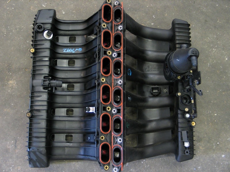 I also installed an M3 (3.2 evo) oil filter housing - this has a thermostat in it, and inlet/outlet ports for an oil cooler (the 328i didn't have this)  Front "clip" drilled and dimpled, then test-fitted     Front wings fitted - these were fit-up to figure out the alignment, etc before everything got painted  Oil cooler mountings welded onto the front cross member piece, and mounted - it was a bit tricky to fit the oil cooler "the right way up" so fitted it upside down with the plan of bleeding it before fitting  And bonnet on - the intent is the oil cooler will sit right behind the front grills   For the oil cooler plumbing, I installed the following.. Tee piece between the oil filter housing and the return line from the oil cooler. This routes to the firewall Its fitted to this line because that port is effectively seeing oil pressure all the time    A line to/from the cooler, the line away from the cooler has a near zero rated (about 0.1psi) check-valve installed, so it only flows back to the engine This was done with the oil cooler the "right way up" and I don't have a picture at this stage but will post one later in the process  This gives you an idea how it looks the wrong way up!  Then inside the car, this happened! (shown here not in its final location)  An Accusump is basically a big (1.5litre i think) piston accumulator with an adjustable nitrogen pre-charge. You set the pre-charge so it gives you a decent volume (around 1 litre) of oil at full oil pressure. The accumulator is tee-d into the oil system downstream of the oil pump such that it supplies oil pressure when the pump cannot.. Think of it as a 1/2 way house between a standard oiling set-up and a dry sump system. There's a choice of "nothing", a fancy electric solenoid valve that comes on/off with ignition, and a clunky big manual ball valve (I went with the latter) This gives full flow through the cooler when hot The return line is always open to the engine/accusump, so is always subject to engine oil pressure (just not always flow) The installation I've gone with is to have.. FILTER HOUSING --- COOLER --- CHECK VALVE --- TEE to ACCUSUMP and FILTER HOUSING So before starting the engine you open the ball valve, wait a few seconds then start the engine. The accusump will provide pressurised oil to the top end of the engine before starting When cold, the accusump operates on the engine side and cannot effect the cooler because of the check valve When hot, the same situation exists but the cooler is in-play (however cannot see pressure from the accusump) The check valve effectively prevents the accusump being able to drain through the oil pump in situations where the oil pump cannot create pressure - this doesn't work when the engine is cold, but not planning on any creating any oil starvation situations when the engine is cold anyway Before turning the engine off, you close the ball valve, and it sits there ready to go for the next time  This is also a going time to point out another upgrade - I actually fitted an E36 M3 Evo sump and dual pick-up oil pump when I rebuilt the engine and forgot to mention it! :lol: This should prevent any starvation anyway (fore-aft) so its really only cornering.. I didn't baffle the sump because a) its a ball ache, b) the only people who sell a kit thats ready to go are in the US and wouldn't ship to a colleague for suitcase-importation or to the UK! c) its not really a 100% fix anyway.. The Accusump isn't either because its a limited volume, however its capable of maintaining about 30psi for 20 ish seconds as its set-up which is pretty good! The other advantage of the "check valve" set-up I have, is the oil pressure switch is acting on the outlet of the pump.. So if it fails, I have a big-bad warning light on the dash, and effectively 20 ish seconds notice WITH oil pressure from the Accusump, but nothing from the pump.. Hopefully its a decent insurance This accusump has some relevant heritage - it was from a mondeo super-touring car.. I was a bit worried my BMW might "reject the transplant" due to the donor being the opposition but so far so good  All cleaned-up and ready for the next stage!  |
|
|
|
Post by smallspeed on Jul 28, 2017 7:09:26 GMT
Engine back in, started work on a few fiddly bits, including starting to think about my least favourite thing - wiring I cut the dash and mounted it to the tabs I'd added to the roll cage before painting. I also fitted the world’s biggest rear view mirror from a golf buggy!   This was a heart in mouth exercise, even with a £30 dashboard, god knows what its like doing it with a £1000 carbon dash, or an unobtainable dash from an old car! I decided I could base the whole wiring around a mini cooper s (r53) engine fuse-box, and so purchased one complete with wiring and fuses/relays from ebay for the princely sum of £15 I then spent about a week figuring out how it works :lol:  I ordered some "offcuts" from an architectual structures company on ebay.. one pack of stainless, one of aluminium - total price was about £25 delivered which was a bargain! This is the stainless..  ..each of those pieces is about 3ft long! Don't really have any in process pics, but I made up a cardboard template and from that this little tray which screws in where the glovebox lived previously  With fusebox fitted..  Then bent-up a cover and painted them both black using some textured black paint, covered with another coat of matt black  Fitted #1  Fitted #2  Fitted #3  And stickered! This sticker is actually from 1992 - I kept it since I was a kid at the final (and EPIC) race of the 1992 season and somehow resisted sticking it on anything!   Around then, THIS happened  This is the same Pi Research System 2 dash used in the works race cars, although they had a "BMW Version" that incorporated a few of the options as standard - back light, BMW ///M stickering, and an amplifier module that can read wheel speed direct from the two rear ABS wheel speed sensors rather than the single diff pick-up (copes better apparently) Back in 1991/2 this was about the same price as a J Reg Granada Scorpio Ghia X, now a days its worth about the same as a J Reg Granada Scorpio Ghia X  In all seriousness though, this was the reserve of the elite back in the day (along with the ridiculous Bosch Motorsport ABS system with a pump the size of a henry-hoover). People used to ask how Vic Lee's M-Team Shell / Listerine race team could afford such things in BTCC - I think we know now!  I will do a post at some point and cover some of the history of the cars, the team and THAT RACE  So to mount this, I brought a set of dead clocks from ebay for a few quid, destroyed them, and then fitted out the back of the binacle with a piece of carbon fibre sheet This was painted matt black, and then mounted up with the dash gauges, and plonked in the dash - perfect fit!  I also made a small panel to cover the middle vent/radio area of the dash  |
|


 )
)


